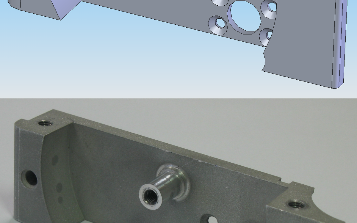
A casting can have enough material overall and still lack stock on a feature that must be machined. FARO CREAFORM's CAM2 update makes this an earlier inspection decision by adding handheld 3D scanning to workflows already used with portable measurement devices.
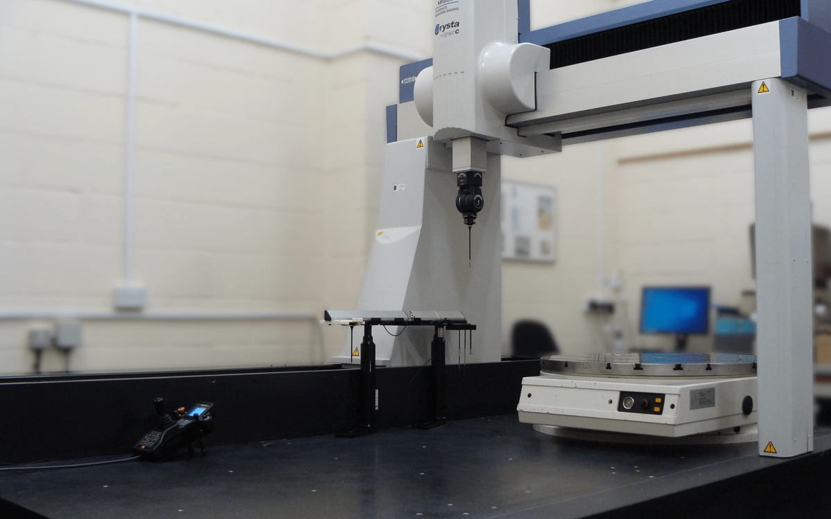
The release extends the CAM2 inspection environment to FARO CREAFORM handheld 3D scanners alongside FaroArm portable CMMs and Vantage laser trackers. The goal is a connected path from capture through CAD comparison, geometric dimensioning and tolerancing analysis, and report generation.
Three additions are particularly relevant to foundry-to-machining workflows: Smart Alignment, enhanced colour mapping and virtual cross-section analysis. Smart Alignment is described as using advanced best-fit methods and material-distribution optimization, helping evaluate where the available casting stock sits relative to the finished geometry. Cross-sections make it easier to review selected internal or inaccessible zones in the digital model.
Best fit is not always the same thing as the production datum scheme. A global alignment that minimizes overall surface deviation may mask insufficient stock on a critical machined feature. Engineers should define which locating surfaces or datums control the machining fixture and examine the material envelope against that same setup. Imagine a casting that will receive three accurately machined mounting faces. The machining planner needs enough stock on all three, not simply a best-fit surface match across the whole exterior. A scan can reveal whether one face has insufficient material once the correct production datums are applied. That information may change how the blank is located, whether a fixture needs adjustment, or whether the part should be rejected before machining begins. This is where the software's alignment and section-analysis functions have the most direct commercial value.
Material allowance is a datum problem
The best-looking CAD alignment is not necessarily the one a fixture can use.
Such decisions also depend on the casting's condition when it is scanned. Excess flash, scale, support features or a surface coating may influence what the handheld instrument records. If software automatically accepts an alignment, the quality team still needs to check that the alignment is physically valid for the intended fixture. When inspection results are used to release material for expensive machining, saved scan data and the selected CAD revision should be traceable to the exact casting.
Colour maps are useful for spotting deviations quickly, but their interpretation requires discipline. A large colour difference on a noncritical cast surface may be acceptable, while a small shortage of material on a precision mounting face can make the part scrap. Those decisions should follow the drawing and process plan rather than a visually appealing scan.
The scan must survive the handoff to machining
The software may also reduce repeated setup work by keeping measurements from different devices in a consistent inspection environment. That benefit depends on calibration, shared coordinate systems and reliable revisions of the CAD model, particularly where more than one department or supplier handles the component.
For the machine shop, the most valuable outcome is an early go/no-go decision on a particular casting, backed by the correct machining datums and saved scan records. Avoiding an impossible machining job may matter more than collecting an additional view of the blank.